「$gatebias」:修訂間差異
跳至導覽
跳至搜尋
無編輯摘要 |
無編輯摘要 |
||
| 第9行: | 第9行: | ||
i.e. -0.3 -0.2 -0.1 0 0.1 0.2 0.3 | i.e. -0.3 -0.2 -0.1 0 0.1 0.2 0.3 | ||
< | <big>'''The $gatebias setting for 1D-DDCC in GUI interface '''</big> <br> | ||
[[檔案:1d_$gatebias_fig1.jpg|1300px]] | |||
<big>'''The $gatebias setting for 2D-DDCC in GUI interface '''</big> <br> | |||
Press '''Contact Setting''' and set up the bias of the gate contact as needed!<br> | Press '''Contact Setting''' and set up the bias of the gate contact as needed!<br> | ||
[[檔案:2D_gatebias_fig1.jpg|1200px]]<br> | [[檔案:2D_gatebias_fig1.jpg|1200px]]<br> | ||
於 2024年9月24日 (二) 13:56 的最新修訂
To determine the bias added to the gate contact.
It should be written in one row with three numbers which represent the start of the bias voltage the end of the bias voltage and the step size of the voltage in sequence.
For example:
$gatebias
-0.3 0.3 0.1
This means that the bias of the gate contact will starts at 0V and increases 0.1V every step until the gate bias reached 0.4V.
i.e. -0.3 -0.2 -0.1 0 0.1 0.2 0.3
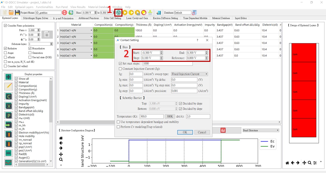
The $gatebias setting for 1D-DDCC in GUI interface
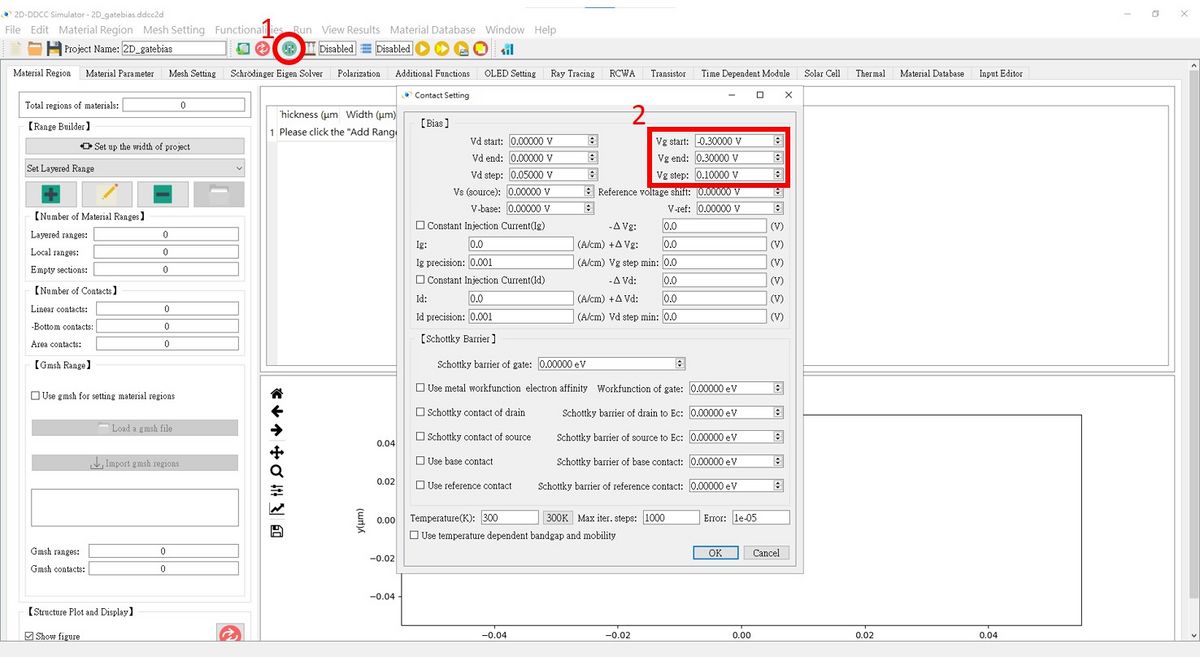
The $gatebias setting for 2D-DDCC in GUI interface
Press Contact Setting and set up the bias of the gate contact as needed!

