$gmshlineboundary
This is functional when the input file is a .msh file generated by gmesh . List the surface numbers in the Gmesh file. The parameters setting is related to each surface in sequence.
Format
$gmshlineboundary
n
line_number type
line_number type
line_number type
Parameter Explanation
line_number : The line number where to put the contact.
type : The corresponding contact type. 21 gate contact. 3 source contact. 4 drain contact.
Example
$gmshlineboundary
6
35 21
36 21
37 21
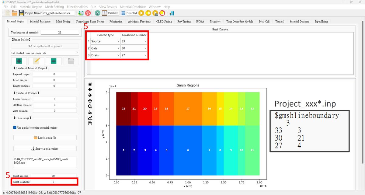
The $gmshlineboundary setting in GUI interface is here
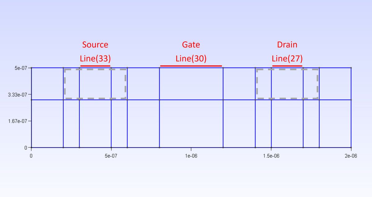
Here's an example of a Gmsh file created for the MOS. The gray dots and blue lines represent the points and lines from the Gmsh file.
The gray box shows the area where doping is assumed, and the red lines are meant to be used as linear contact lines.

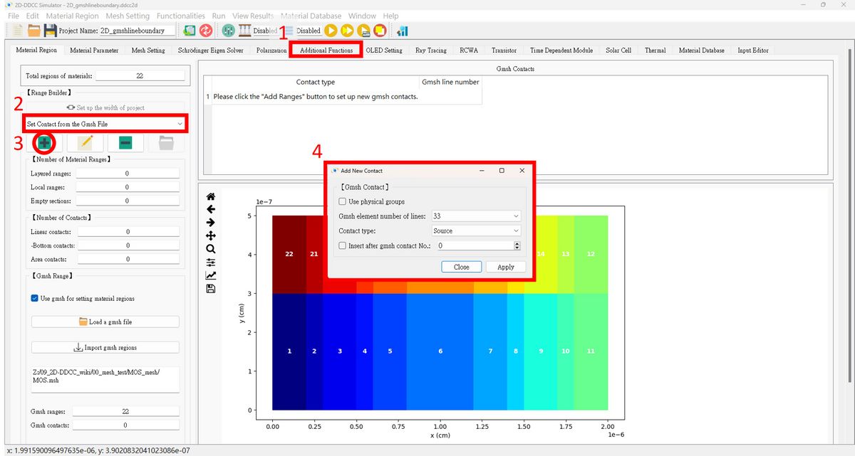
1. Press Additional Functions.
2. Load a Gmsh as process like $gmshsurfparameter.
3. Press Set Contact from the Gmsh File.
4. Please set up the fields as needed!

5. Here are the Gmsh lines selected as contacts, and the number of contacts is displayed below.
